Heating Facility Transmitter
last update:16jun15
Sections:
Terminology:
- tx names:
tx1,tx2,tx3,tx4,tx5,tx6
- antennas: 5 Mhz
- 1a(tx1), 1b (tx2), 3a(tx3),3b(tx4),5a(tx5),5b (tx6)
Intro: (top)
Page to keep track of heating facility
(hf) calibration.
Tx Names: 1 through 6.
- 5.Mhz dipoles tx1-6 = D1a,D1b,D3a,D3b,D5a,D5A
- 8 Mhz dipoles tx1-6 = D2a,D2b,D4a,D4b,D6a,D6b
There is a 100 kw dummy load that can be attached to the output of a
transmitter. It includes a calorimeter to calibrate the 60db coupler
after the tx output stage.
Current Issues (may15)
- get each transmitter outputting to 100Kw on dummy load
- make sure we can protect the receivers in dome, ch when hf is
transmitting.
Daily Measurements: (top)
- 150504:
- dummy load tx4:
- monitor cable was hooked up incorrectly on coupler.
- Saw broad band glitches on dummy load
- strong harmonics around 128.125 Mhz. go away when rf drive
turned off
- banging on solid state amp caused power levels to jump
- tx1,2 on antenna. 327
rcvr results:
- looked like no power output from tx2
- 5.125 harmonics seen at 327. tx1
- 150506
- rf monitor cable hooked up correctly (but still used spare
cable)
- dummy load tx4
- monitor cable hooked up correctly (still used spare cable)
- 327 rcvr sees hv on, does not see 5.125 harmonics at full
power into dummy load.
- Measured the fundamental and up to 6*F0 on the spectrum
analzyer at drive=3.05 dbm
- looked at 0 to 500 Mhz with hipass filter in. 128.125
strongest harmonic.
- Tx1,Tx2 on antenna (327
rcvr)
- tx2: no power seen.
- tx1:
- 5.125 harmonics seen at -20dbm rf drive
- broad band glitches seen at -15dbm rf drive
- 1 sec spectra: 10 times Tsys
- 1 millisec spectra: 100 times Tsys
- 327 recovers after glitch in < 1 millisec
- some glitches not resolved in 1 millisecond spectra
- No N*60Hz seen in the spectra of the total power.
- 150507:
- dummy load tx1,tx4
- new monitor cables installed
- calibrate the spectrum analyzer and rf drive values using
the dummy load.
- tx1 1 measurement (probably bad) then burned resistor in dummy load
tx 1
- calorimeter
measurement tx 4
- 150508:
- dummy load
- tx2 dummy load moved to tx1. Burned resistor in tx1 dummy load.
- dummy load tx3: output temp meters differed by +3C .. stop
testing
- redo calorimeter
measurement tx 4
- 150512
- dummy load
- prior to tests, replaced output temp sensor on tx dummy
load 1 and 4.
- they had different values from the other 2 when no power
applied
- water temp on dummy load stable 29 to 31 degC for entire
run
- tx4 calibration
- tx3 calibration:
- tx1 calibration
- 4 measurements then powerdip, ran out of time.
- dana took 1 ghz bw timedomain samples of a burst with tek
scope
- 150513
- tx4 on antenna:
- brought up to rf drive:-3.2, fwd meter:18kw, reflct:1kw
then tripped
- tripped at this level reliably.
- 150514
- tx4 on antenna
- added 1db,2db atttn to reflected power to forestall
trips
- Got to 30kw, rfdrive:-1.3 dbm then tripped on reflected
power
- measured refl pwr: 1kw (actual 2db higher)
- it is tripping on 1kw measured reflected power.
- tx6 on antenna:
- drive to +2dbm, rf meter:32kw, reverse power measured 0.
no tripping
- saw harmonics to 40*Tsys(in 1 channel), and occasional
spectra with ripples of 1 Mhz to 6*Tsys
- the harmonics did not seem to increase with output power.
- 150515:
- try to adjust the reverse power trip for Tx4
- 150518
- 150519
- adjust tx 4,5,6 meters
- tx 6
AT9 attenuator bad, replaced with 3 other
- tx5: power meter bad. Replaced with spare. Readout scale
not linear
- 150520:
- adjust meters tx1,tx2
- tx1 +15 volt supply card a2 has 3Volt pkToPk ripple. Dc
voltage 16.4 volts.. need to fix
- tx2: 26volt supply ps1. no output. not band select. need
to replace.
- 150521:
- adjust meters tx2
- the 26 volt supply was working today. So we calibrated the
meters for tx2
- 150522:
- tx5 pwr meter. fixed the old one and reinstalled. so scale
is now correct
- re calibrated meters
for tx5
- dummy load tx6,tx5
- did dummy load calibration for tx6
- So no broad band bursts on dummy load.
- tx 5. did not get much power out . looks like drive stage
way low.
- ran 80KW into dummy load tx6. monitored coupler 0 to
500 Mhz saw no broad band bursts.
- 150525
- 150526
- 150527:
- tx3: measure loss in cable from 60db coupler to control room
(1.22 db). also measured the delay
- computed xmitted pwr vs coupler output with and without
cable loss (see 150527 below)
- need to refit dummy load data including thee 1.22 db cable
loss.
- tx6 on antenna
- took data with alfa bm 0 while xmitting
- az,za 360,15.. xmitted to 100kw.occasional bursts
- az,za 240,15 .. xmitted 100kw . occasional bursts
(stronger than az=360)
- but this may have been lightning. 1,2 usec stw peaks not
obvious.
- 150602:
- tx1 on antenna. to 100KW
- tx4: won't come out of filament delay state
- tx6: on antenna, to 100 KW
- take data with alfa bm 0 for
- move to 430 dome, measure harmonics, for about 5 minutes
- 150603:
- tx4 on antenna
- trips at 25 then 50 KW, reflected power.
- lots of bursts
- looked at front panel ports with scope
- had arcing at top of ant for tx4
- tx3 on antenna
- 150610
- tx5 on dummy load
- at 70KW tripped
- saw driver anode oscillate on scope before trip. alfredo
things this is a loose cable.
- tx2 on dummy load
- at 45-50kw tripped . drvr A ac flt
- saw jump on ipa output on scope at trip.
- broadband amp showed no jump
- . but needed more diagnosing...
- 150611
- tx4 on dummy load.
- saw no bursts. ran 60 to 90 kw for about 1 hour
- got trips drvA Ac fault at 95kw (3dbm drive, then later at
2.7 dbm drive)
- 150612: dana used fd/tdr to measure tx3b coax
after arc repair.(.pdf)
- 150616:
- tx5
- driver tube capacitance bad.. replaced outer sleeve
- capacitor on pa output replaced.. only had about 160kohms.
Wouldn't hold 5KV (normal working env has 13kv across it).
- 150618: first light
daytime: tx1,3,6 (dipoles 1a,3a,5a)
- we ran tx 1,3,6 to the tangential dipoles: 1a,3a,5a
starting around 17:07 ast
- power level was about 60KW in each tx
- 150619:
- 150623:tx 4 on dummy load
- dana measured S11 tx4 heliax to dipole 3b. saw broad
reflection (40ns) at far end.
- ran tx 4 dummy load, measured power, calorimeter
- recorded values (including pa cathode current) in table.
- drive power needed was about 4db higher than previous.
- tripped with PA Amp DC around 87KW.
- After trip, drive power needed was 3.5 db less than before
trip?
- Eventually found connectors on back of broadband amp were
loose. AFter a trip, the vibration probably changed the
power getting into the next tubes...
- 150629: tx2, tx4 on dummy load
- tx2
- trip drv AC Amps at 3dbm drv. coupler: 9.5dbm +1db
- adjusted biases.. then brought back up. tripped at same
drive level
- Then standby -> hvOn standby light wouldn't
go off
- tx4 dummy load
- did calorimeter checks. got to 17dbm coupler value.
- At 17dbm coupler output tended to wander 16.6 -> 17.0
- 150820: measured
heliax 3b after further repair.
- removed damaged heliax. cut it at bottom of balun and then
spliced in a new piece.
- 150909: tx 5 on dummy load.
- couldn't get more that 15kw out. ipa filament voltage was
4.5 volts instead of 7.4.
- Broadband amp increased to saturation, but ipa up didn't
increase much..
- 150915: 2,4,6 on antenna. arcing
in heliax tx3b transmitter 4.
- monitor with ch and interim correlator
- bring 2,4,6 up to 60 kw .. saw glitches
- 2 up , 4 down, bring up 6, then increase 2 a little to be at
60kw
- start bringing up 4 , trips at -7 dac drive, this was
arcing..
- pictures of arc:
- pictures of inside of balun showing arc was between
outside of heliax and the inside of the balun.
- bring back up 4, 2, 6 way down
- dac drive 4 -10dbm.. specana says 8kw.. before it -10 was
about 25-30 kw.
- bring down 4, run 2,6 at 75 kw for about 20 minutes.
- ch mon looks like 4 was arcing..
- 150918: 5,4 on dummy load
- calibrate 5 on dummy load
- calibrate 4 on dummy load
- 1/2 way through bringing 4 up (specan-10.73 22kw), gain
jumped up by 4db .. and stayed there
- ran 5 for 10 minutes at 90kw
- ran 4 for 5 minutes at 90kw
- 150922: heliax from tx 4
repaired. dana does vna measurements
- 150928: high pot test of balun section.
- we did a high pot test of a 5 foot section of balun. The
setup was:
- outer conductor of heliax with spacers, pushed into
section balun (see pictures)
- we used the sband high pot
- we first used a new 5 foot piece of balun, we then redid the
tests with the 5 foot section that had the arc in it (see pictures). We then repeated the test with
the damaged section after wetting it.
- The results were:
-
section
|
arcing
Voltage
|
notes
|
new
|
20 to 25kv
|
- arcs at spacer closest to front of section
|
damaged
|
23 kv
|
- heard buzzing noise start around 18kv (probably
corona from damaged spot)
- arc did not start at the front most spacer. It
probably started at the bad spot
|
damaged
wet
|
10kv
|
- with a spray bottle, we sprayed a small amount
of mist on the front most spacer.
- high pot current started immediately, arcing at
1st spacer started at 10kv.
|
-
- We also measured about 23Mohms between the outside of the
balun and the heliax outer connector (a second measurement
gave overload on the fluke meter).
- Summary:
- the burned spot caused corona around 15kv
- A good section holds about 20 to 25Kv before arcing
- the arcs occur at the frontmost spacer
- Arcing is very sensitive to a small amount of water..
- dana never found the gremlins inside the balun...the
spacers got in his way....
- We should compare these values with what we get when the
entire helix is in place inside the balun on tower 3b
(before and after connecting the dipole. We can do this from
the splice.
- 150929: measure resistance between
balun and outer conductor of heliax.
- The heliax was reinstalled in balun for dipole 3B.
- The short to the heliax outer conductor was removed as well
as the top of the heliax was disconnected.
- We measured the resistance between the outer part of the
heliax with the balun.
- The resistance was open (infinite) and then jumped to .6
ohms when we moved the bottom portion of the heliax.
- labeling the balun 5 foot sections 1.. 8 counts from the
top:
- we removed section 7 and 8.
- At the top of section 7 we saw that the heliax was bowed.
- The spacers had slid on the heliax when the heliax was
installed in the balun.
- We put more spacers at this point and then reinstalled the
balun. The resistance went to infinity.. But we didn't know
if the heliax was still bowed, only that it wasn't touching
the balun.
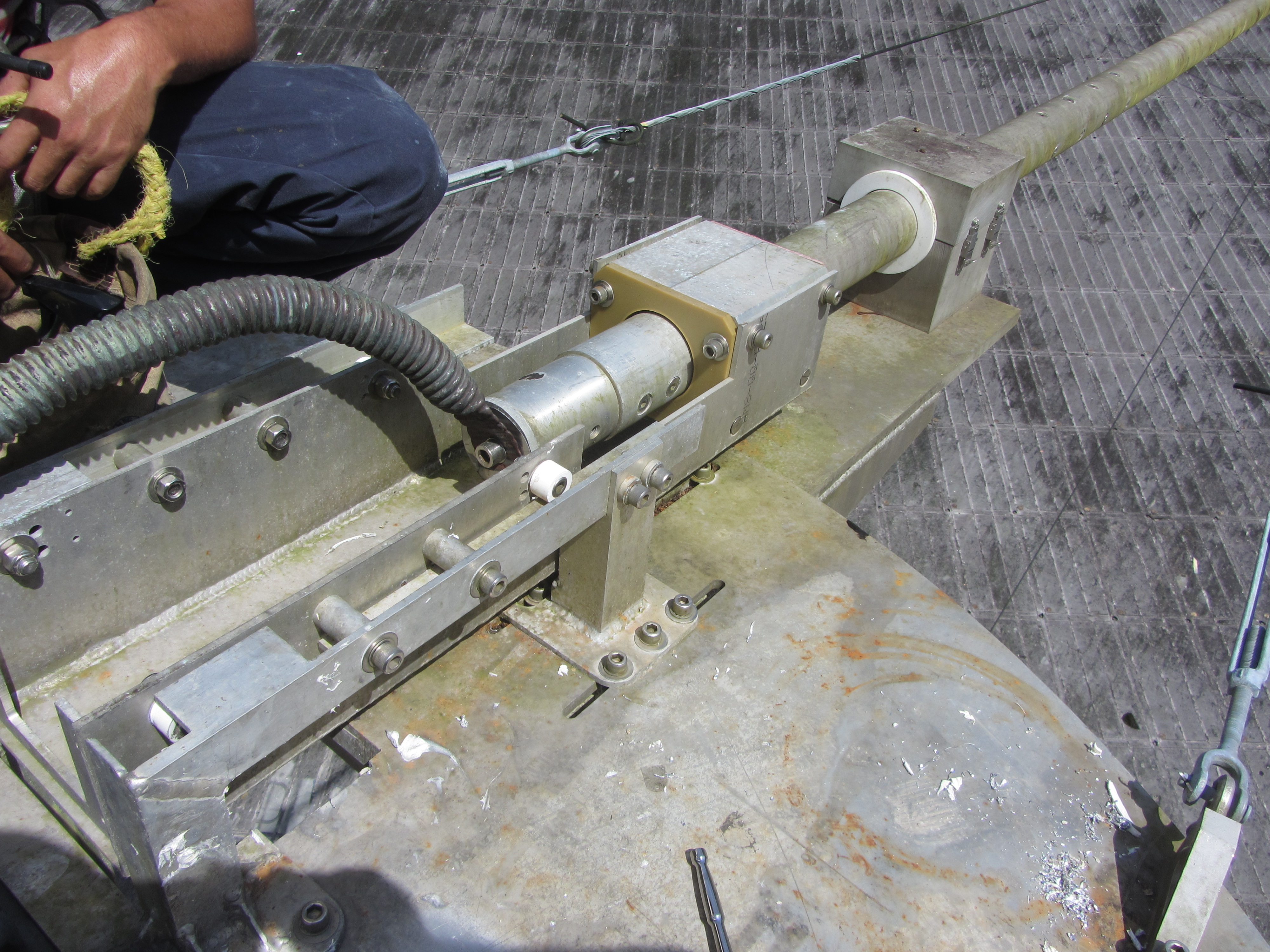
- 150930: time domain measurements
of balun, heliax. (also see 150930 pictures)
- The vector network analyzer (vna) was used to check if the
heliax was well centered in the balun. If the heliax had a bow
in it, we should see it on the return echo on the time
domain measurement.
- setup:
- vna at ground level, 70 foot cable to adaptor that
connected to the outer ring of heliax at top of balun.
- bottom of balun was shorted to the outer ring of the
heliax.
- The time domain measurement showed bumps along the balun.
The first was about 20 feet from the top.
- Results of measurement:
- We decided that we needed to remove all sections of the
balun and then reinstall them 1 piece at at time rather than
pushing the heliax (with spacers) through the entire balun.
- The sliding of the spacers is probably what caused the arc
in 15sep15. All the other baluns were installed 1 five foot
section at a time about the heliax. After tx3B burned,
the spacers were shaved to make them slide easier and the
heliax was pushed through the entire balun after it was
assembled. We are now going back to installing one piece of
balun at a time about the heliax.
- See pictures of sma cable to heliax outer connector at top
of balun.
General measurements/tests: (top)
Measured rf levels (top)
We measured the 5.125 Mhz radiation levels
using the narda monitor (get model #) while testing the hf
transmitters.
These were single transmitter tests.
date
|
transmitter
|
transmitted
power
|
location
|
measured
level
|
150602
|
1
|
96KW
|
visitor center balconey
moved to find largest signal
|
50microWatts/cm^2
|
150602
|
6
|
100KW
|
edge of dish,inside ground
screen
|
5
milliWatts/cm^2
|
Dummy load calibration measurements and
curves (top)
Linear fits were done to the calorimeter
measurement vs rf coupler output (linear values).
- 0 coupler power should be 0 calorimeter power. this implies
y-intercept should be 0
- There are 2 output temp meters. I fit computing the
calorimeter power from: the average, tout1 only , and
tout2
only.
- The color of the final table, corresponds to the fit i used.
- The ratio of PwrKw/pwrCouplerLinear should be a
constant. I threw out outliers
- Calorimeter measurements with low output power were not very
accurate (hard to read the meters with enough accuracy).
- Data prior to 150512 were ignored. They had high input
temperatures (fans not working correctly).
- This data is fit to the 60db coupler as it is read in the
control room with the anritsu spectrum analyzer. I used the
values read off of the analyzer... no cable loss corrections
were made. So you should be able to use the values straight off
of the spectrum analyzer when using the plots.
Output power (at 5.125 Mhz) vs
60db rf coupler (using coupling constant) (.ps) (.pdf)
Dana's measurements (top)
Jim's documents (top)
Tx documentation (top)
txDoc links:
tx-schematics
tx manual
parts list
other site preparation
tetrode doc
ab5 tube performance computer
- tx-schematics
(.pdf) from alfredo
- p33. 1-24 signal monitor circuit card assembley 1A1A2
- fwd,rvs det pwr smp, and clip adjust
- tx manual
(.pdf) from mike
- both manuals are in the same .pdf file
- pnnnn is the page number in the .pdf file
- Manual 1:Technical manual:
operation and maintenance instructions:Transmitter
Group
- p5: start
- p13: table of contents
- p19: list of illustrations
- p25: list of tables
- p37: chapter 1: General
Information
- p103: chapter 2:Installation (not present)
- p105: chapter 3:Preparation for use and reshipment. (not
present)
- p107: chapter 4: Operation
- p107: section I Controls and indicators. 4-1 to 4-4
- p155: section II:Operating Instructions. 4-5 to 4-9
- p189: section I? Emergency operations 4-7
- p191: chapter 5: Theory of
operation
- p191: section I: Functional System. 5-1 to 5-4
- p195: section II:Functional Operation of Electronic
Circuits. 5-5 to 5-9
- p263: chapter 6: Maintenance.
- p263: section I: Organizational and Intermediate
Maintenance. 6-1 to6-9
- p520: 6-238 table 6-21 Freq Range and max
acceptable vswr
- p549:section II: Special Maintenance. 6-10 to 6-14
- p774:section II : Performance Test Checks (see next
manual, p1355)
- p775: glossary
- p797: index
- Manual 2 :: Technical manual:
Operation and maintenance instructions: Radar Transmitter
- p821: start
- p825 table of contents
- p827 list of illustrations
- p832 list of tables
- p843 chapter 1:general
information 1-1 to 1-25
- chapter 2,3 not present
- p879 chapter 4:Operation
- p879 Section 1 controls and indicators (4-1 to 4-4)
- p925 Section II maintenance operating instructions
4-5,4-6
- 4-6 maintenance operation
- p935 section III emergency operation and shutdown. 4-7
to
- p937 chapter 5 theory of
operation
- p937 Section I: Functional system theory of operation
5-1 to 5-2
- p941: section II: Electronic circuit description. 5-3 to
5-16
- p989: section III: Functional mechanical operation: 5-17
to
- p997: chapter 6
Maintenance
- p997: section I organizational maintenance. 6-1 to 6-6
- p1024 6-4 trouble shooting
- p1026: transmitter Meter readings, Benchmark.
- currents, voltages, and allowable error
- p1032: control diagram cross reference. led/fault
description -> ref designator
- Start of Control diagrams
- p1038: band A control diagram
- p1084: reverse power control diagram
- p1097 6-5 General removal and installation
- p1097: 6-5.2 Control/Status cards
- p1104: 6-5.3 Broadband amplifier
- p1105: 6-6.4: control voltage supplies
- p1111: 6-5.5 rf arc sensor ad internal cca
- p1112: 6-5.6 ipa grid bandpass filters
- ..... omitted
- p1180:6-5.25 directional couplers
- .....
- p1225: 6-6 Electrical checks,tests and alignment
procedures
- p1225: 6-6.1 Arc sensor sensitivity adjustment
- p1225: 6-6.2 RF band output test
- p1226: 6-6.3 Alignment procedures:
- p1226: 6-6.3.1 Power supply tests/adjustments
- p1229: 6-6.3.1.1.2 +26V dc power supply
- p1229: 6-6.3.1.1.3 +15V dc power supply
- p1229: 6-6.3.3.1.4 +/- 15 V dc power supply
- p1230: 6-6-3.1.2.1.1 ipa screen grid overload
adjust
- p1231: 6-6.3.1.2.1.2 driver screen grid overload
adjust
- p1233: 6-6.3.1.2.1.3 pa screen grid overload
adjustt
- p1234: 6-6.3.1.2.1.4 ipa anode power supply
overload adjust
- p1235: 6-6.3.1.2.1.5 driver anode power supply
overload adjust
- p1235: 6-6.3.1.2.1.6 PA anode power supply
overload adjust
- p1237: 6-6.3.1.2.2.1 PA AC current
overload test
- p1237: 6-6.3.1.2.2.2 driver AC current overload
test
- p1245: 6-6.3.1.2.2.3 IPA AC current
overload test
- p1248: 6-6.3.2 variable transformer 2T224
adjustment
- p1249: 6-6.3.3 RF feedback control CCS 1a1a1 and
Signal monitor CCA 1A1A2 test/adj
- p1249 1. calibrate forward power meter
- p1249 2. calibrate reverse power
meter
- p1277: section II special maintenance. 6-7 to 6-9
- p1355: section III Performance test checks. 6-10
- p1367:reverse power trip test procedure
- p1395: index
- reverse power trip: page 1367 sect 6-10.2.5
- parts
list (.pdf)
from alfredo
- other site plans (.pdf)
.. from mike128Mbytes
- 4cw150000E
tetrode documentation (.pdf)
- eimac_ab5_tube_performance
computer (.pdf)
miscellaneous
- 150603:
Dipole 3B (tx4) arcs at end of coax where it
connects to wires going to dipole.
- we were xmitting about 50KW on tx4 when we started to arc at
the end of the coax.
- more info shows that
the arc was continuous for about 6.7 minutes
- The pictures show the teflon spacers at the end of the coax
center conductor and the plastic cover that keeps the rain
out.
- pict 1 (.jpeg)
- plastic cover and 1 spacer
- pict 2 (.jpeg)
- plastic cover and teflon spacers
- The center conductor of the coax comes out the top of
the plastic connector and goes to 1 side of the dipole
- The hole blasted in the cover is where the other wire
fron the other end of the dipole connected to
the outside of the coax..
- pict 3 (jpeg)
- looking inside the plastic cover
- pict 4
(jpeg) pict 5 (jpeg)
- outer sleeve and inner conductor at end of transmission
line. This was cut off of the end of the line before
replacing the connector. The spatial is in units of dana's
hand.....
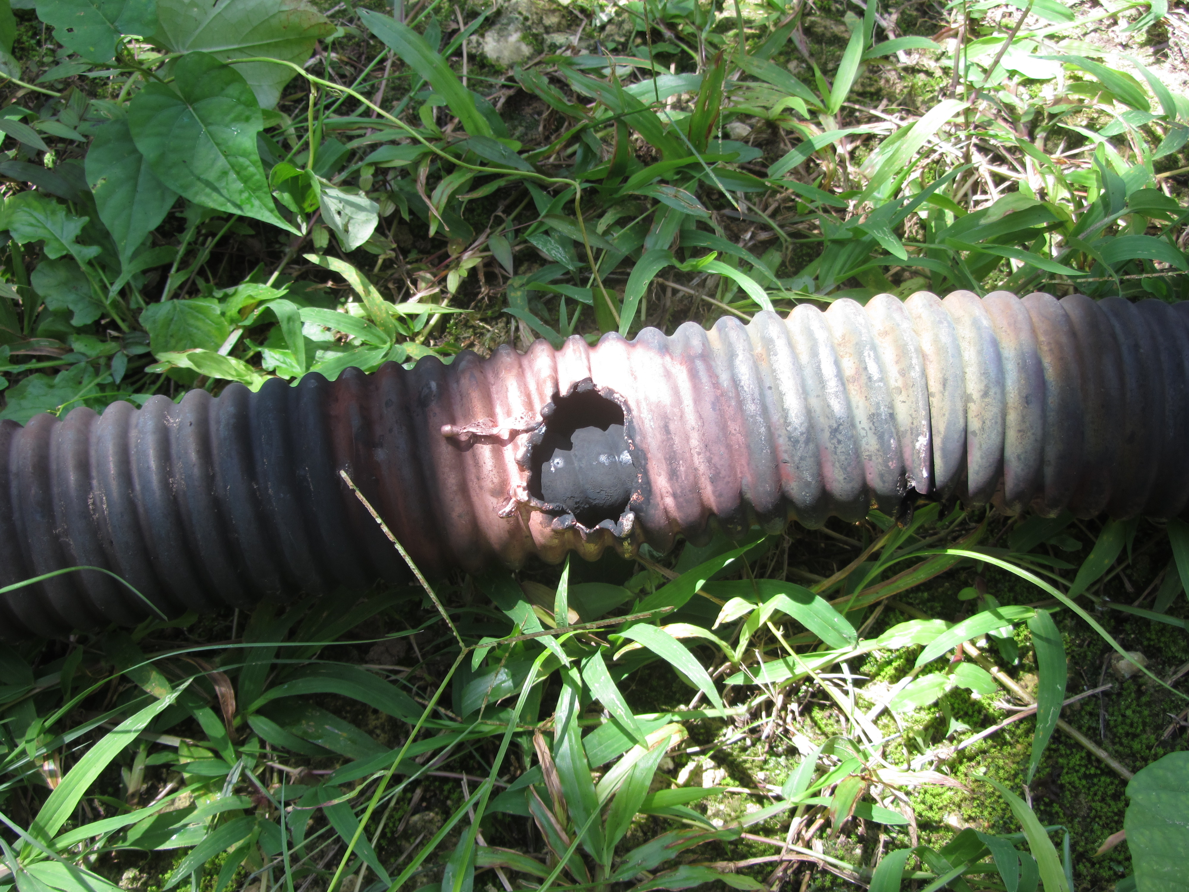
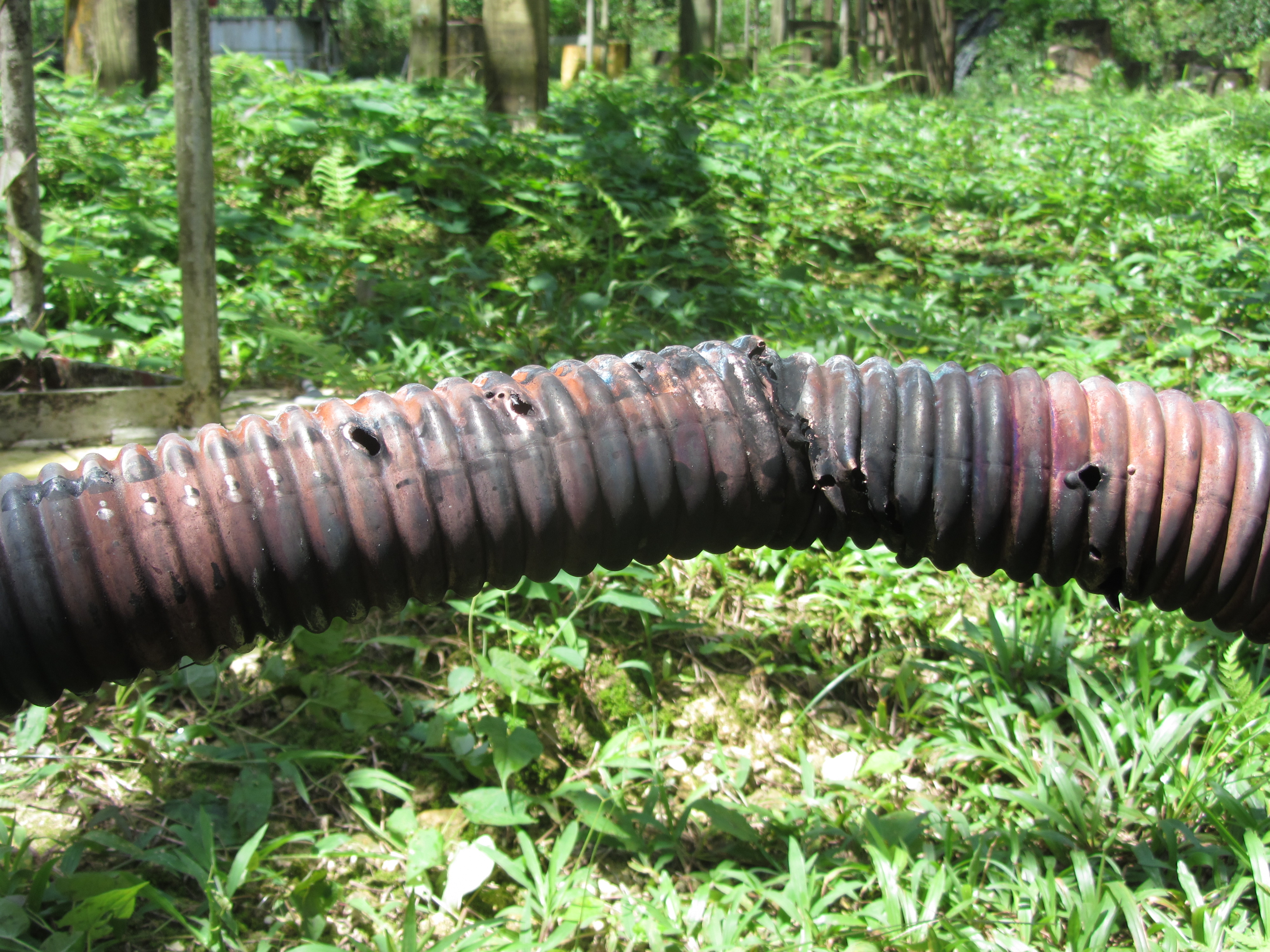
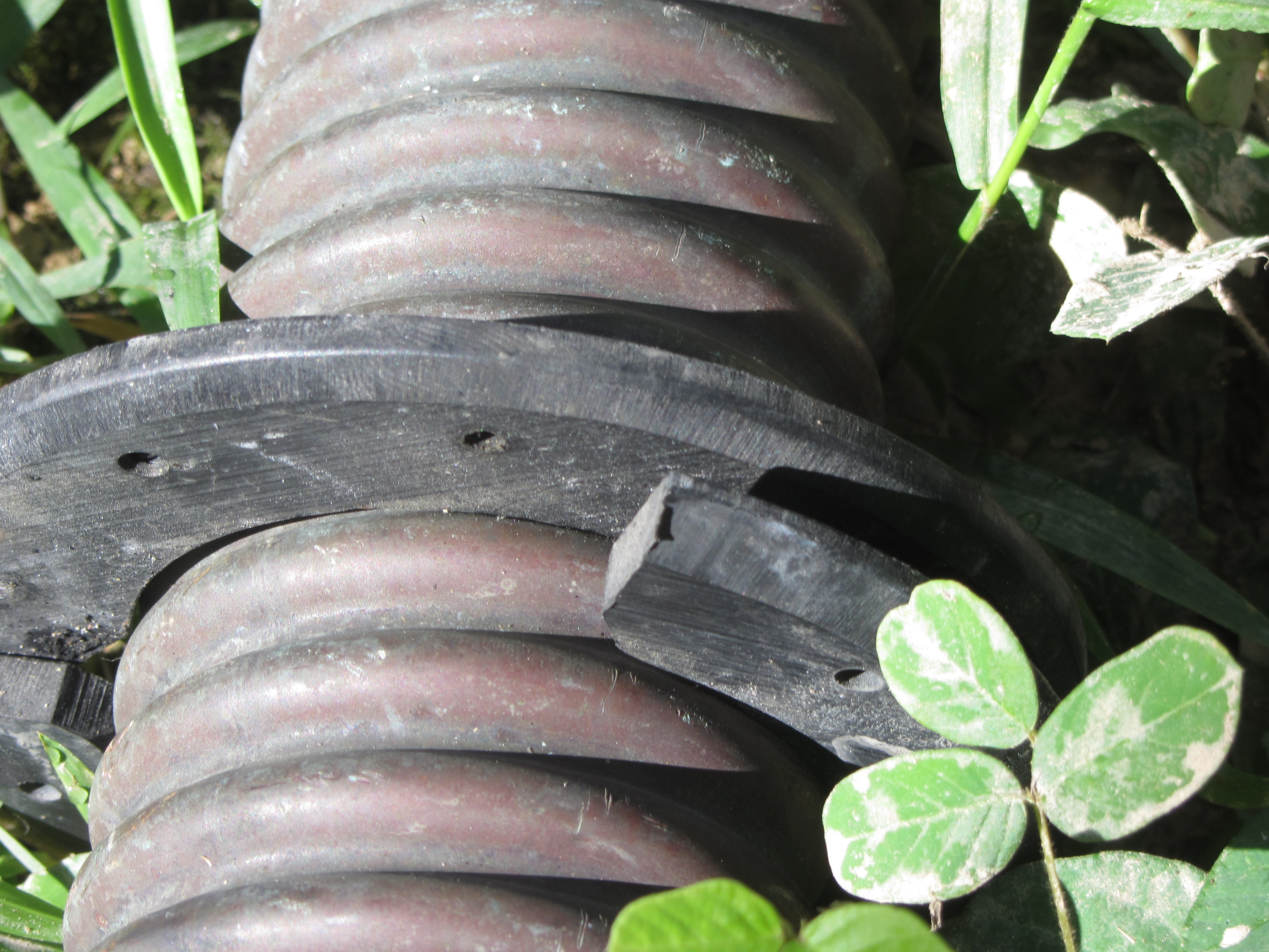
- 150915:Pictures of Dipole 3B (tx4)
arcing at end of heliax.
- dipole 3B (tx4) had arcing on 150915
when we fed the dipole with about 60KW.
- The heliax from the splice up to the dipole connection was
replaced (again). This is about 60 feet of heliax.
- I took pictures of the damaged heliax on 22sep15 as i lay on
the ground close to the ao9 cement base.
- pict1 -large
section of cable stretched out
- You can see the large hole toward the middle
- the cement base to the right of the heliax is about 3 feet
wide.
- The large hole was 24 feet from the lower end of the
heliax piece and about 30 feet from the upper end of the
heliax. There was another 8 foot piece that was also part of
the piece of heliax that was removed (not shown).
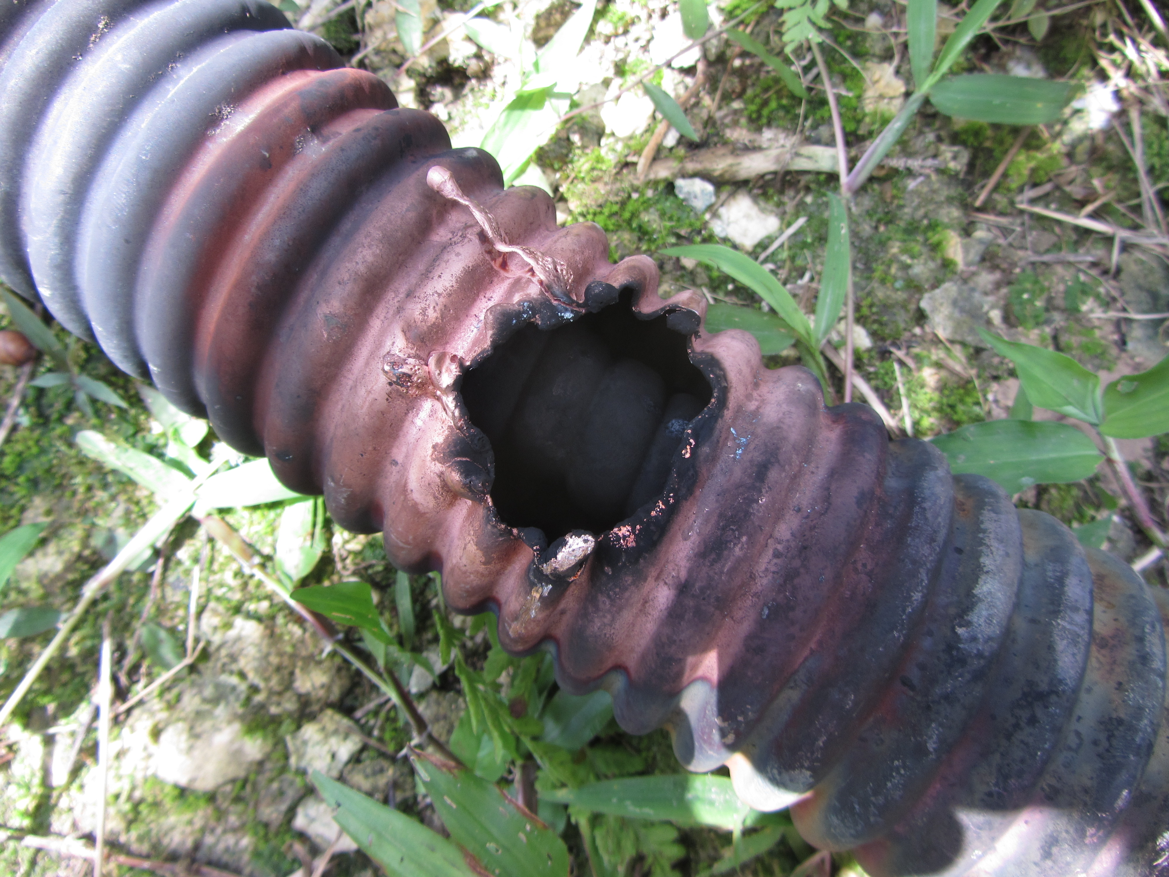
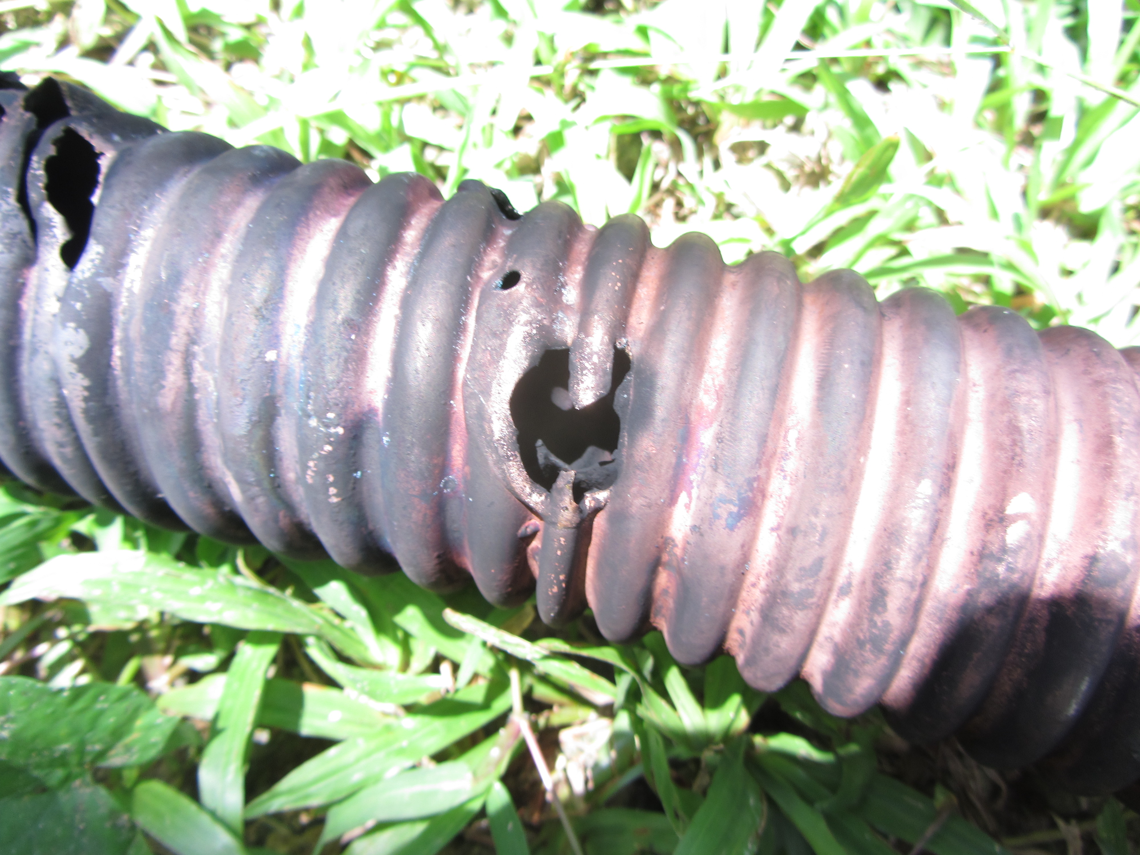
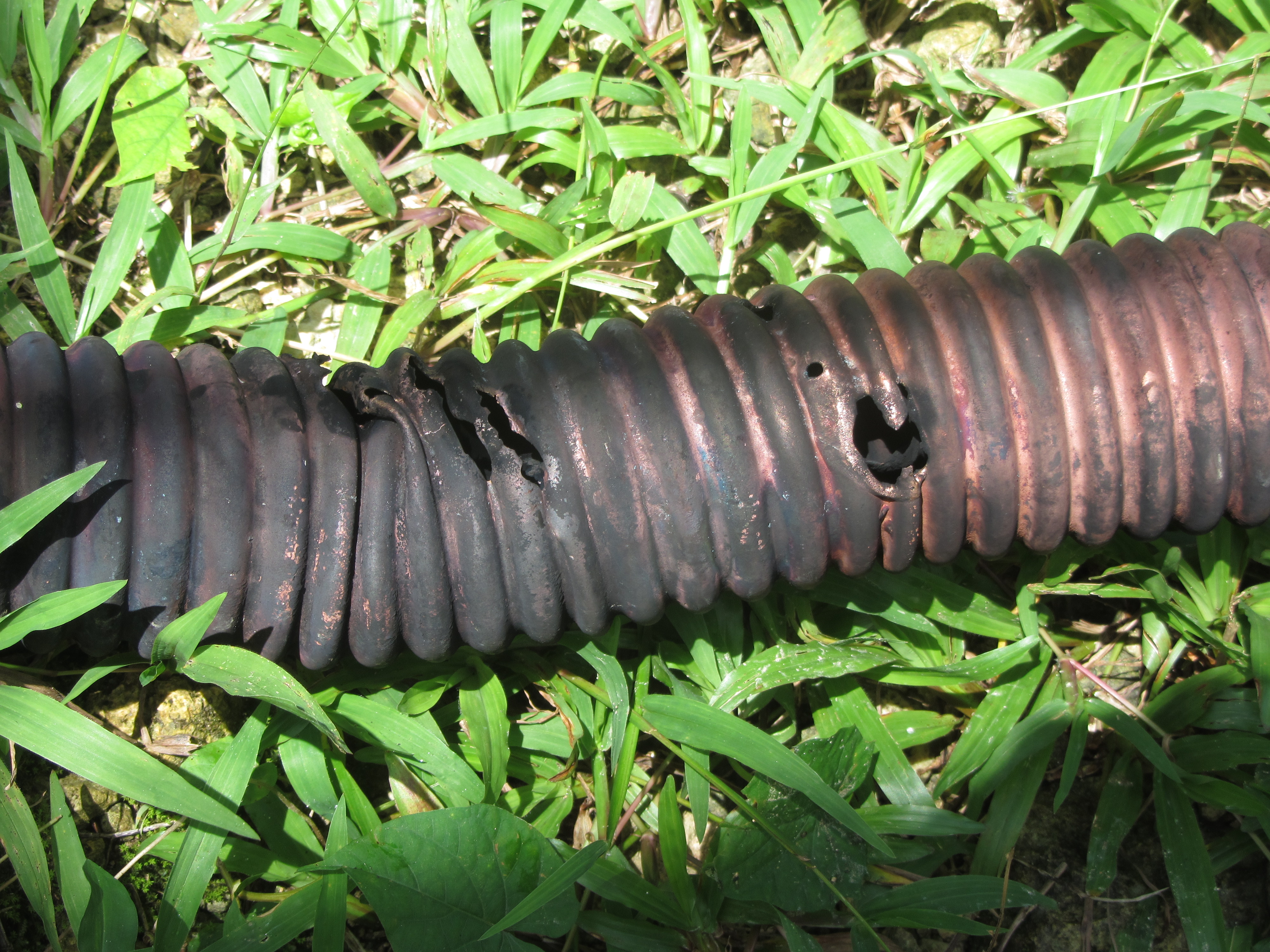
- pict2 -
blowup showing the upper 1/2 of the damaged part
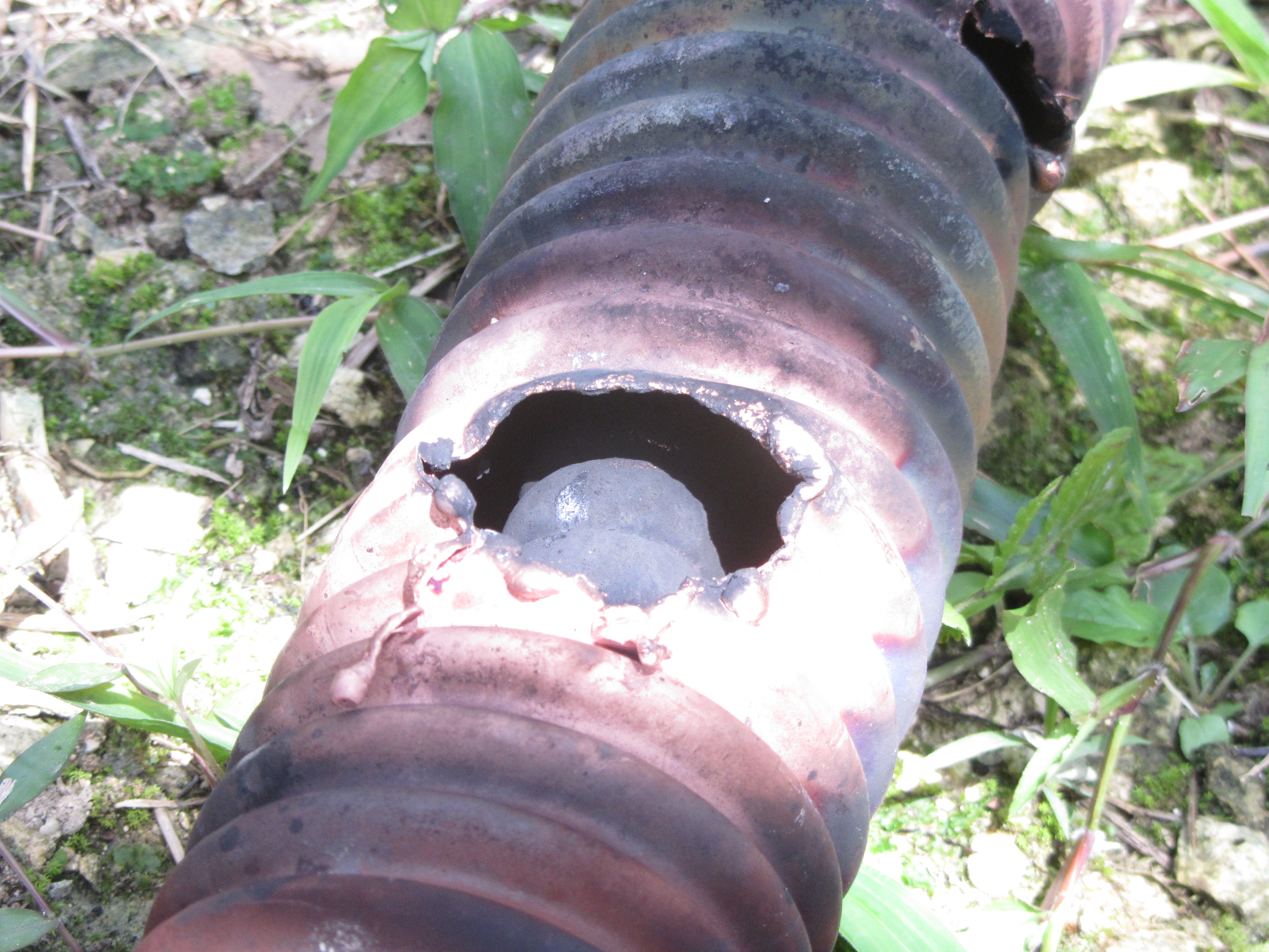
- pictures 3-7 show different angles of the large hole..
- pict3
- pict4
- pict5
over exposed to see inner conductor. It looks intact here,
but about 2 inches to the right of the hole, the inner
conductor is damaged.
- pict6
- pict7
large hole, and smaller hole to the right.
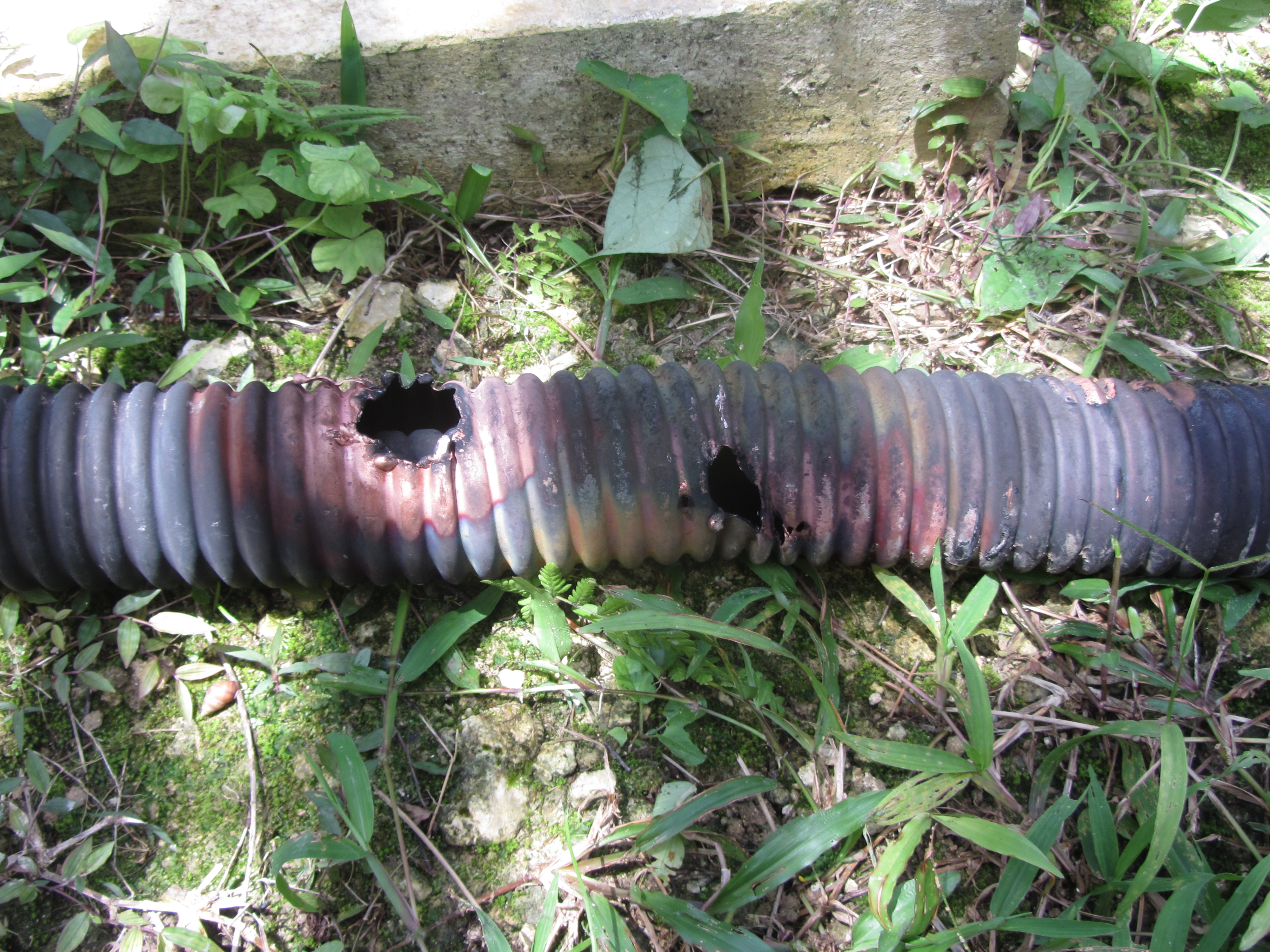
- pictures 8-11 show the damage below the large hole. It
includes a kink in the heliax that was probably created when a
large part of that section burned away..
- pict8
- pict9
- pict10
You can see that the inner conductor is also damaged. This
is true most of the large holes.
- pict11
- there were 8 to 10 separate holes punched in the outer
conductor
- the inner conductor was damaged at most of the large holes.
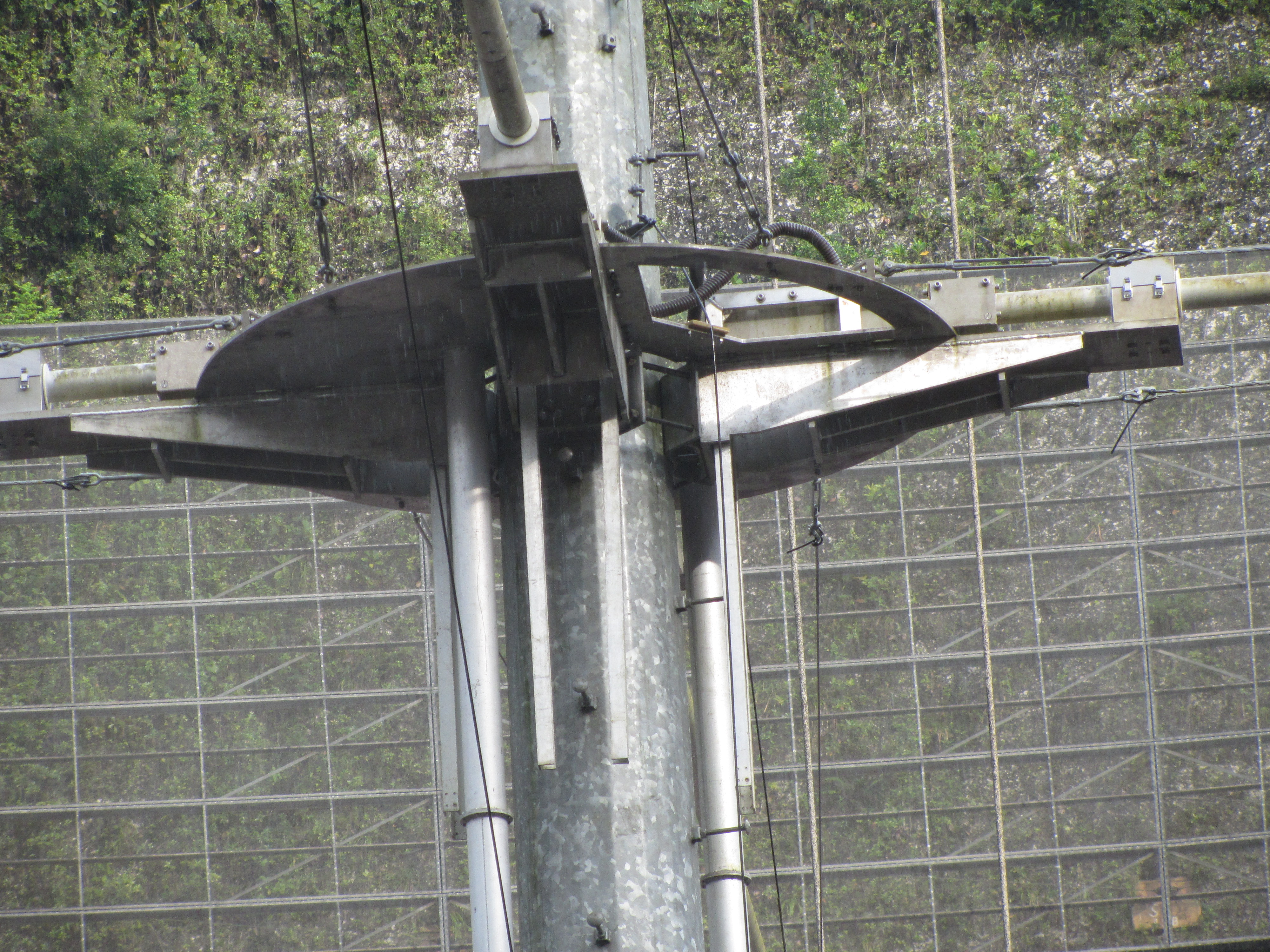
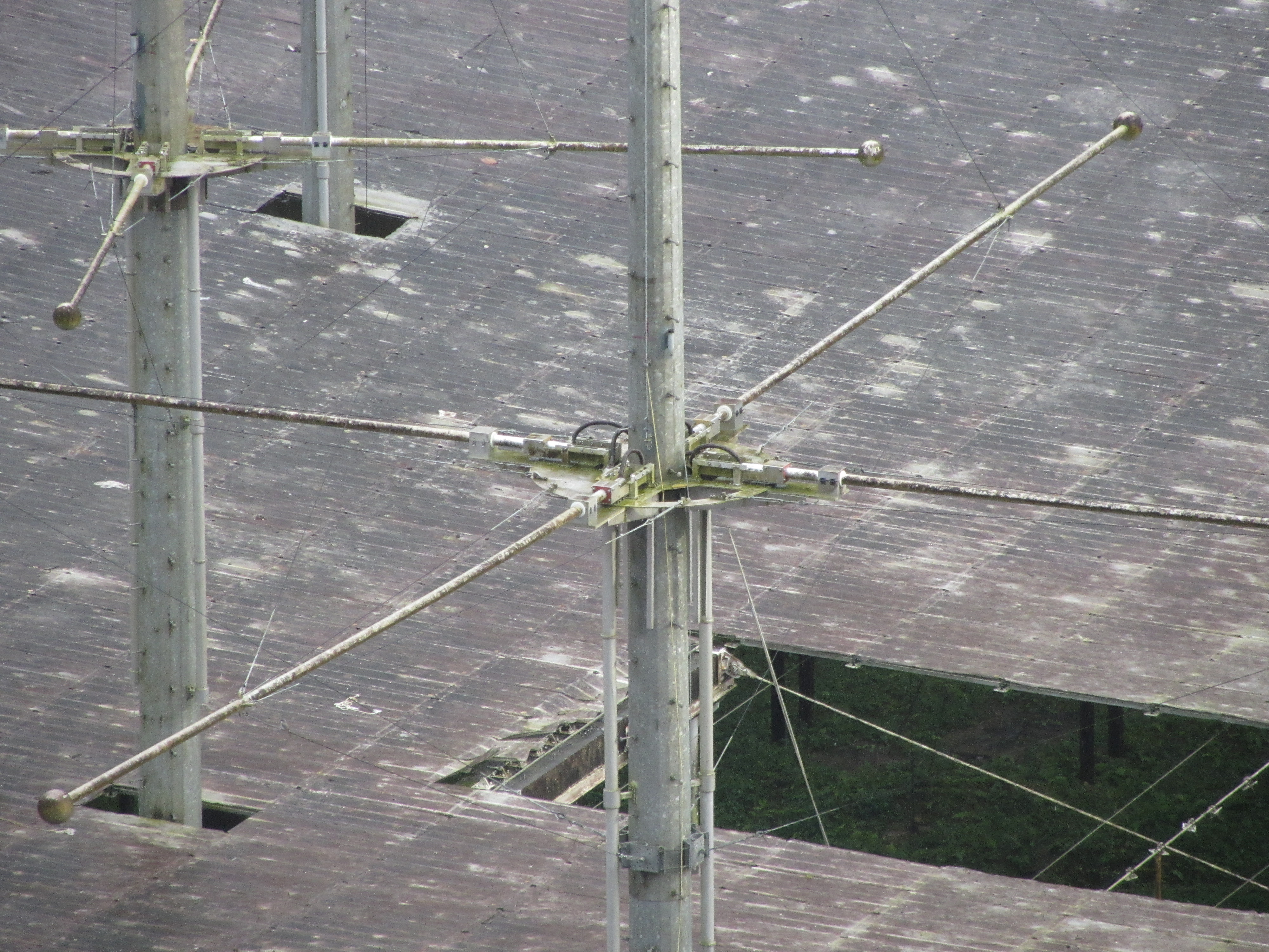
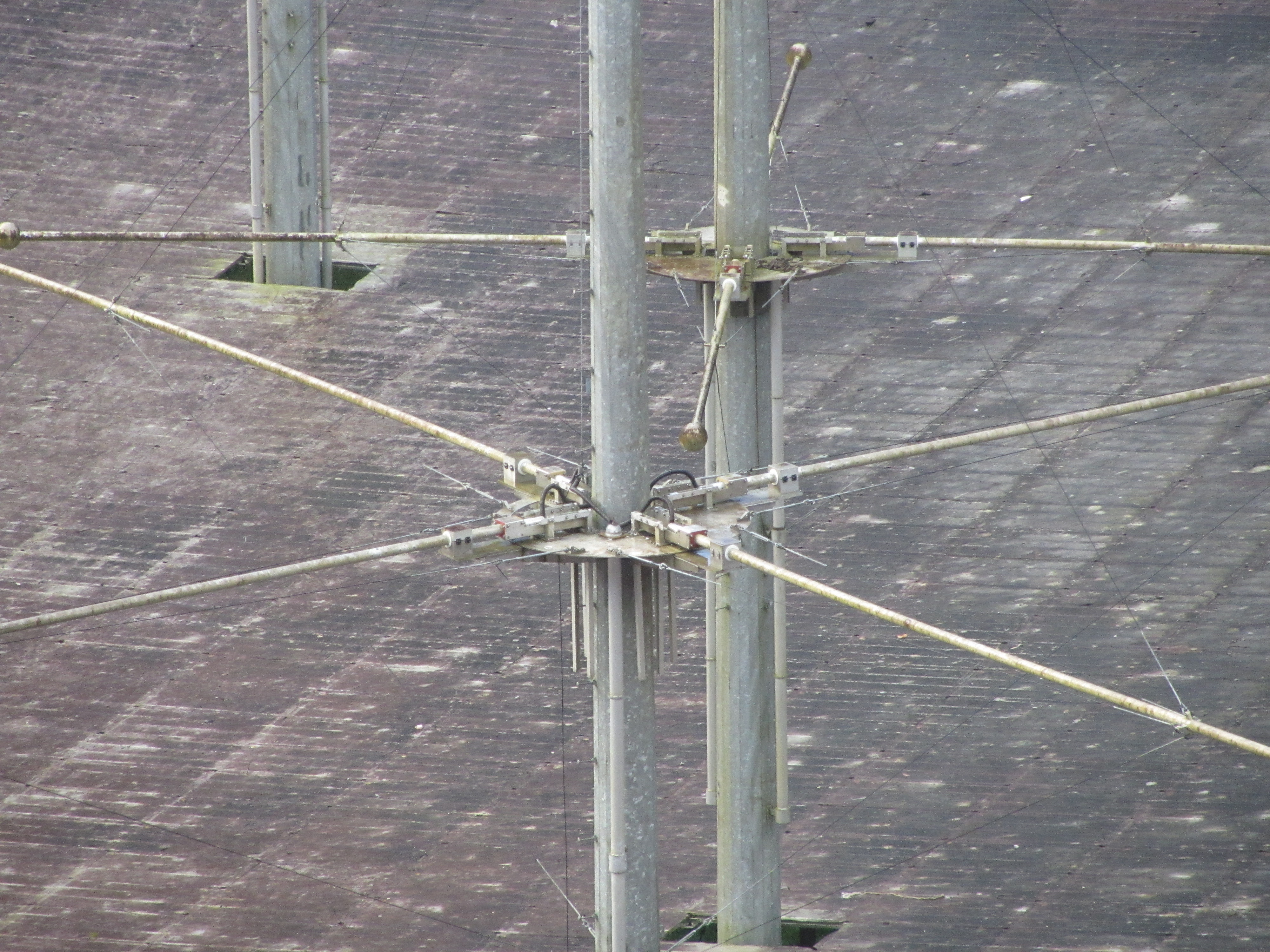
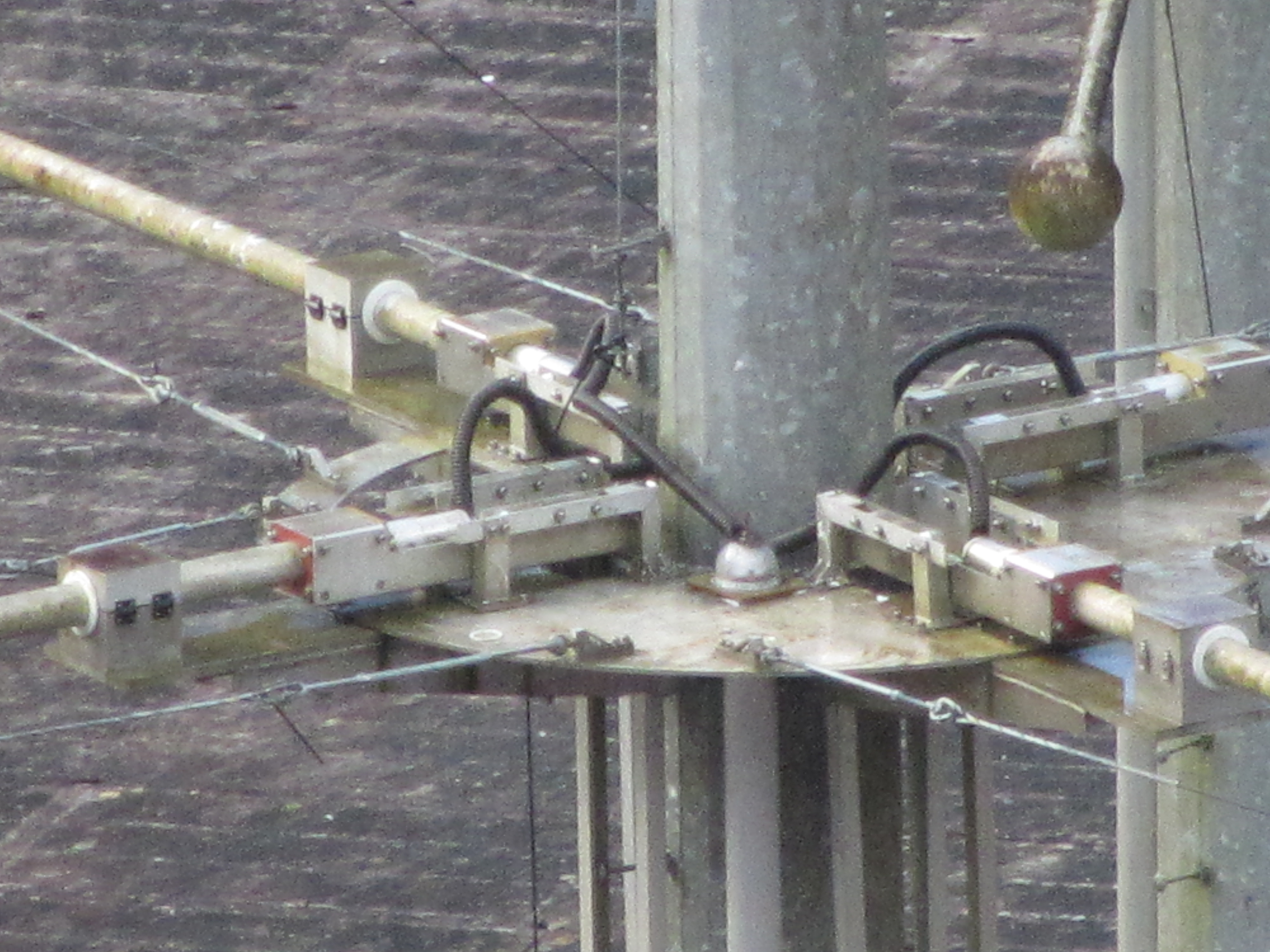
- 150922: pictures of the towers
- Tower 3 from ao9 monument stand
- This is from the center of the dish.
- pict1:
- tube on left is balun for tx3a (transmitter 3). It feeds
the tangential dipoles that are parallel to the image. The
helix that looks to be close to the safety line is
coming from tx3a
- tube on the right is balun for tx3b (transmitter 4) this
is the heliax that is arcing. It feeds the dipole that
comes out of the image (the other dipole is not visible).
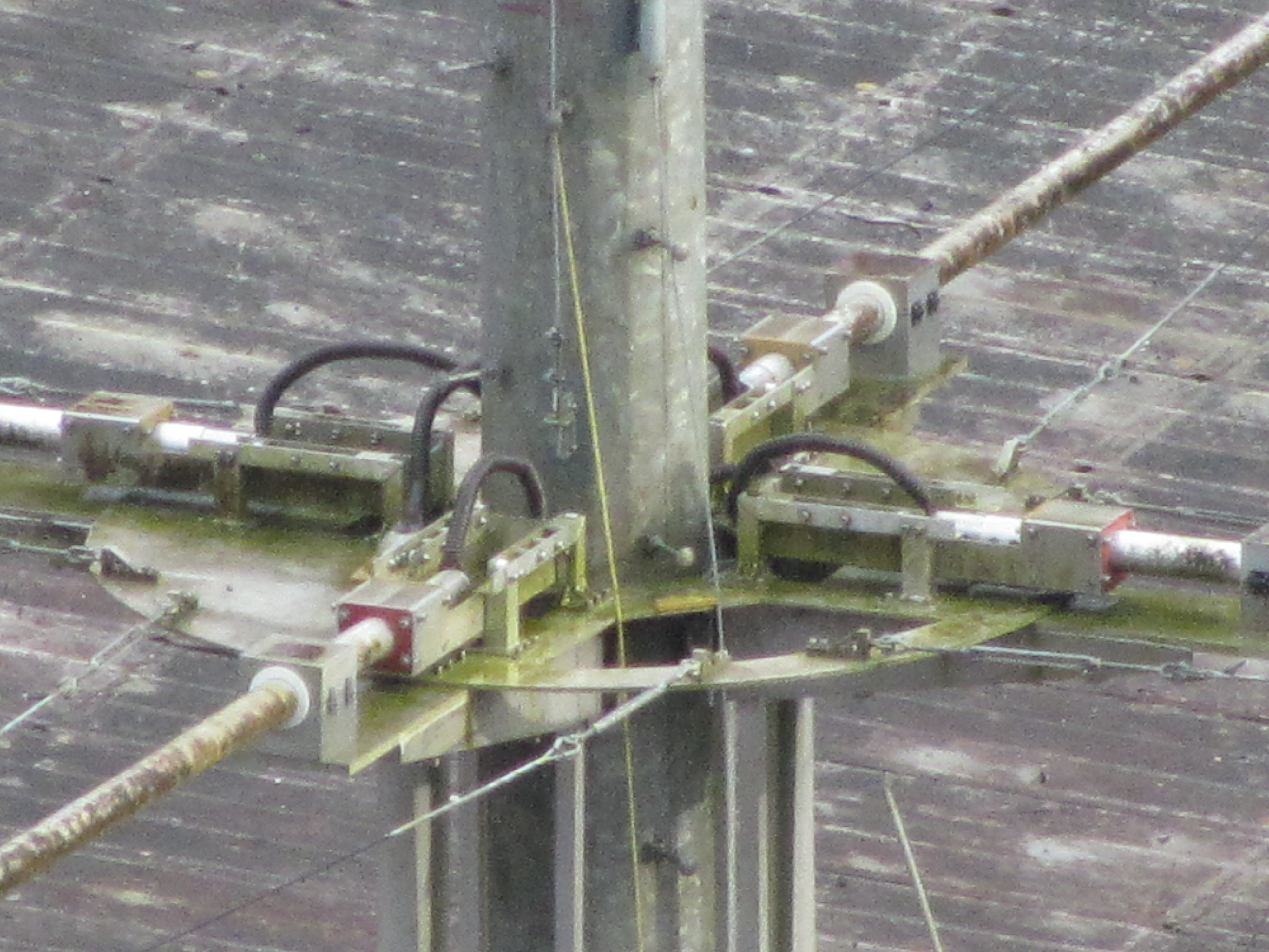
- pict2
- This is a blowup of pict
- the heliax directly behind the safety line is from tx3a
- the heliax above the safety line is from tx3b (that was
arcing)
- Tower 1 from rim road close to road that goes under
the dish.
- pict3
- the dipoles lower left to upper right in picture are the
radial dipoles.
- they are fed by the heliax in the balun on the left side
of the tower.
- The short heliax feeds the half dipole coming out of
the page
- the opposite dipole half is fed by the heliax that
goes around the left side of the tower.
- pict4
- Tower 3 from rim road sitting on the anchor for the
southeast fill area of the dish (it is the foreground tower)
- pict5:
- dipole lower right to upper left (radial dipole) is fed
by the helix in the balun seen in the picture (the other
balun is not visible). This is tx3b (transmitter 4) that
was having the problems with arcing.
- pict6:
- blowup of pict5
- You can see the heliax's coming out of the cap on the
top of the balun feeding the two half dipoles
- 150925: Pictures of inside of dipole
3b balun showing arc from heliax outer conductor
to balun inner surface.
- on 150915 we had an arc in the heliax from tx4 to
dipole 3b (see above), about 24 feet
from the dipole end of the heliax.
- on 25sep15 the bottom section of the balun was removed
(starting from about 19 feet from the end of the balun ..check
this) and brought to the hf building.
- the balun is built in sections of about 5 feet.
- We inspected the topmost section and it looked ok
- We then removed the topmost 5 foot section to look at the
next one.
- The 2nd section looked ok when visually inspected from the
end.. but after reaching our arm in about 2 feet, we could
feel a bump.
- I then used my canon sx70 camera to see if we could get a
better look at the bump...
- pict1
looking down balun from the end
- we marked the outside of the balun where we could feel the
bump on the inside.
- we lowered a masking tape roll this distance (actually a
little extra) into the balun to give us a distance
reference.
- the bump is the black area to the lower left of the tape.
- For pictures 2,3,4 we rotated the balun so that the arc
damage was on the upper right. We then slid the camera down
into the balun directly below the damage to take the picture
(macro mode with 10 second timer)
- pict2
arc damage is centered left,right but falls off the bottom
of the image
- pict3
arc damage is centered up,down but off to the left
- pict4
entire arc damage bump in the picture.
- Looking at the blownup image, you can see narrow ridges
sticking up out of the damaged area and they are bent to
the right. This was probably caused when the heliax
spacers passed over this area when the heliax was removed.
- Pictures 5 and 6 are taken with the camera looking in from
the end of the balun section with the far end illuminated with
the diode floodlamp.
- pict5
- the burned section from pict2,3,4 is more than half way
down from the top of the picture
- there is a white ring before the burned section. This
may be from one of the spacers holding the heliax in the
balun. I'm not sure whether the black area on this ring is
a burn area.
- pict6
- another show from the end showing the white ring and the
main damaged area beyond it.
- Notes:
- We did not see the damaged area on our first visual even
though it was only 2 to 3 feet from the end of the tube.
- We need to think of a better way to inspect the tubes.. We
lucked out this time because the damaged area was only a few
feet away from the end and we felt the bump with our
fingers...
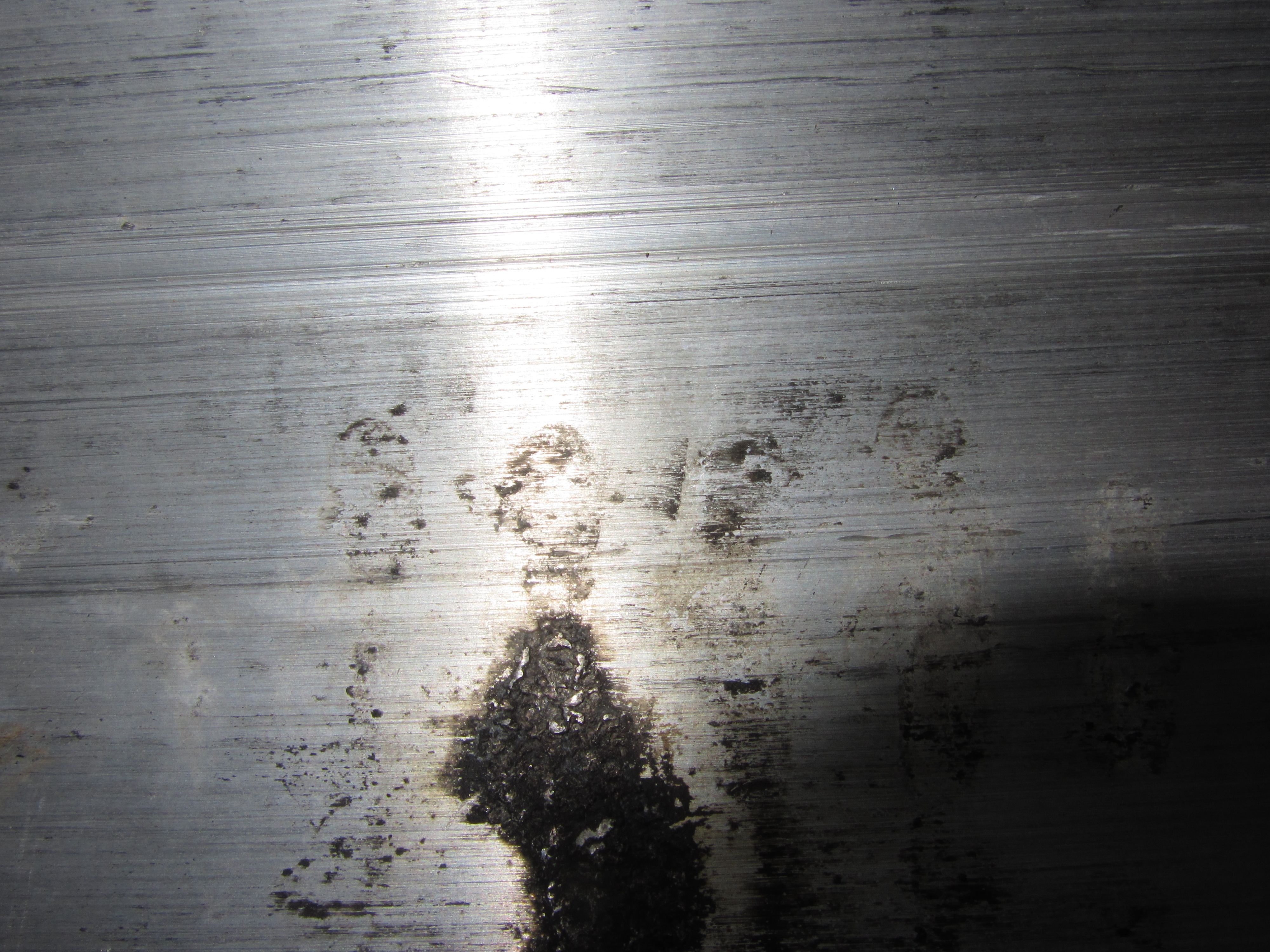
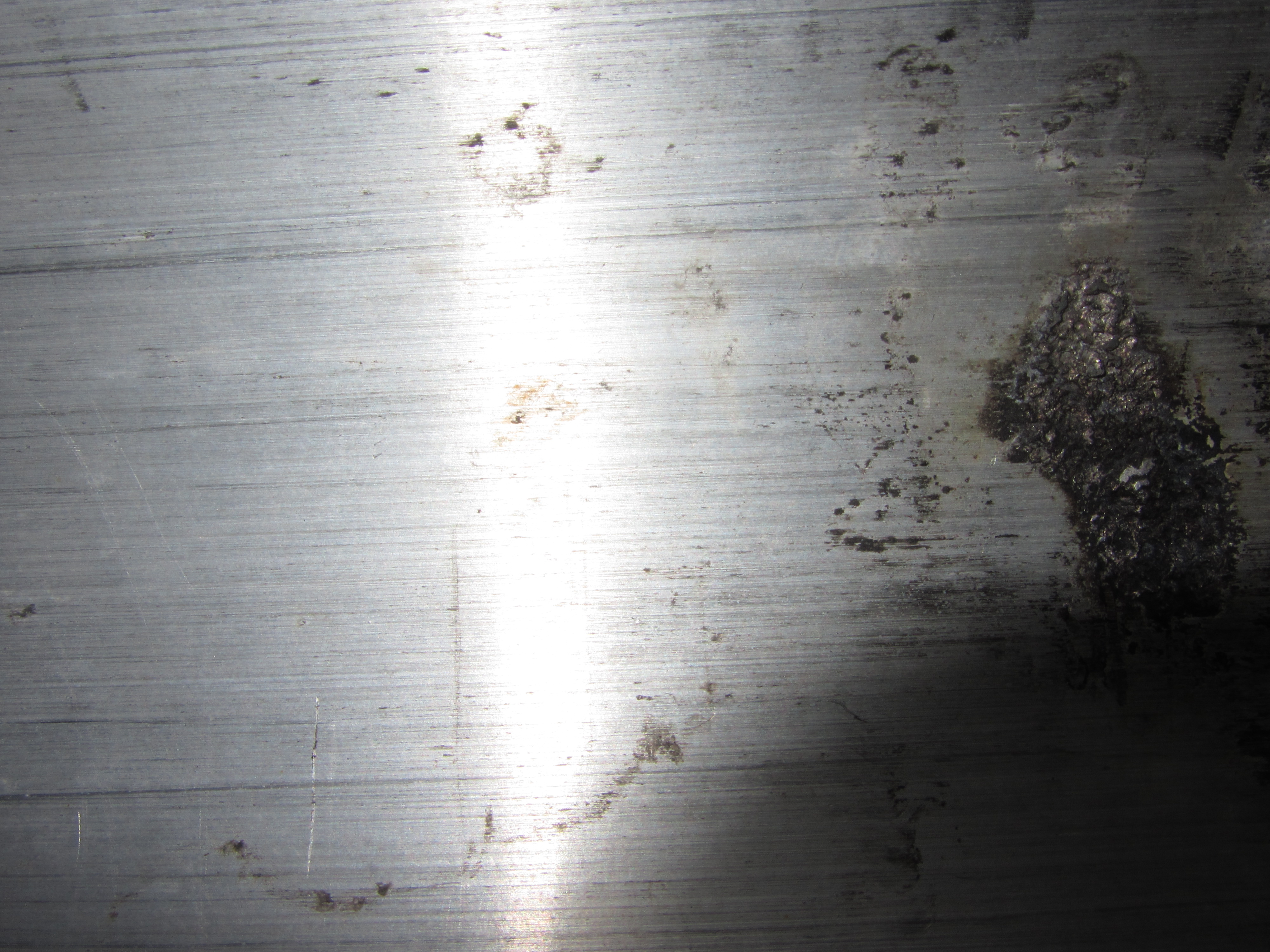
- 150928: pictures of spacers used to
align heliax in balun
- there are two half circles next to each other spaced every
few feet to hold the heliax in the balun. One edge of each
spacer has been sanded down to make it easier to pass the
heliax and these spacers through the balun.
- pict 1 :
picture of spacer
- pict2: blowup
of spacer
- The ends of each spacer is pretty sharp. They are probably
making the grooves we see on the inside of the balun.
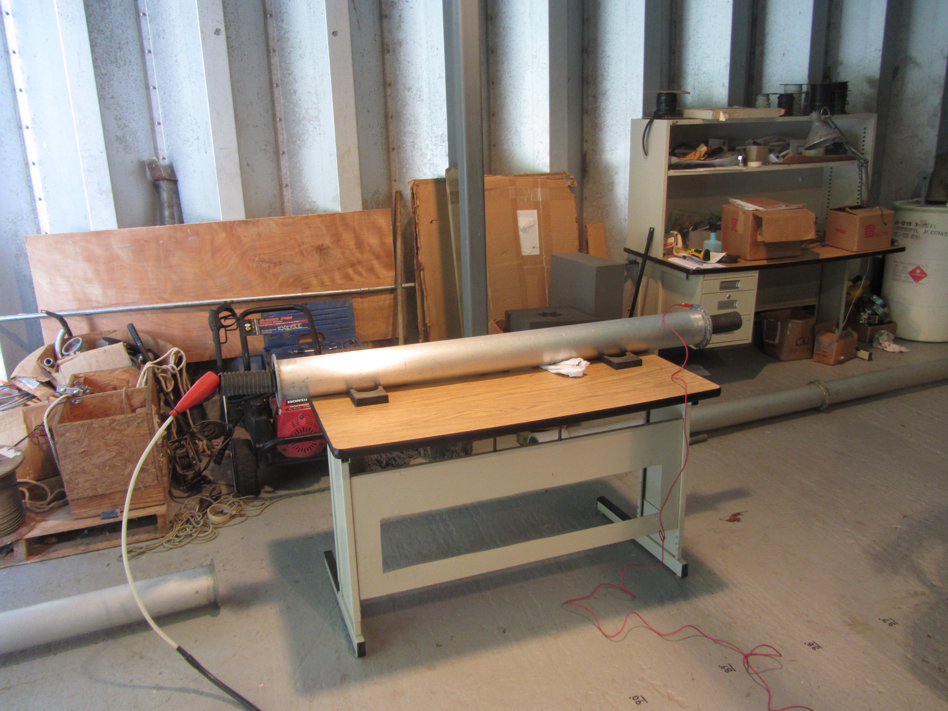
- 150928: picture of high pot setup
- pict1: balun
section with heliax used for hipot test.
- pict2: dana
searching for the gremlins making all the noise inside the
balun.
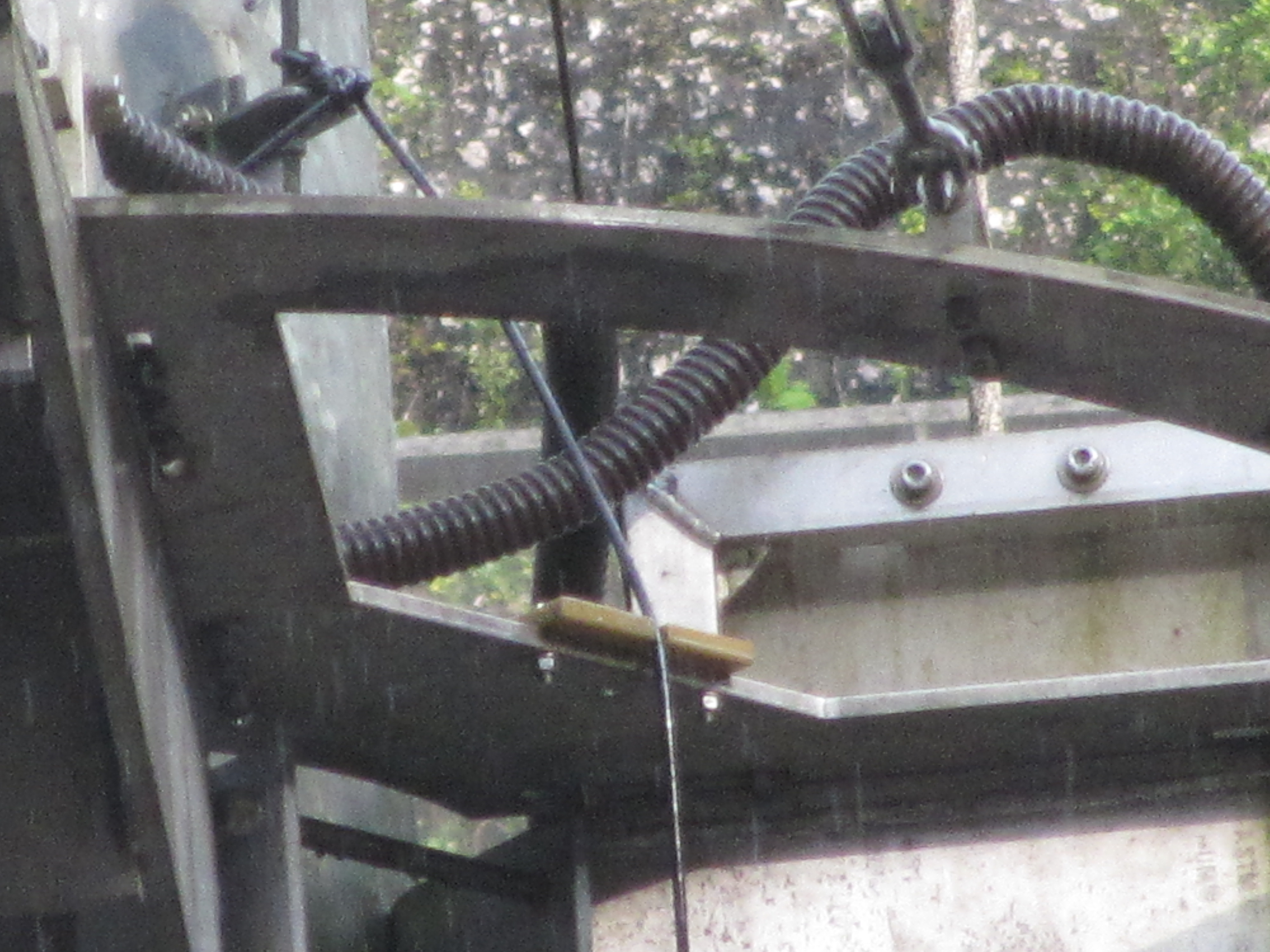
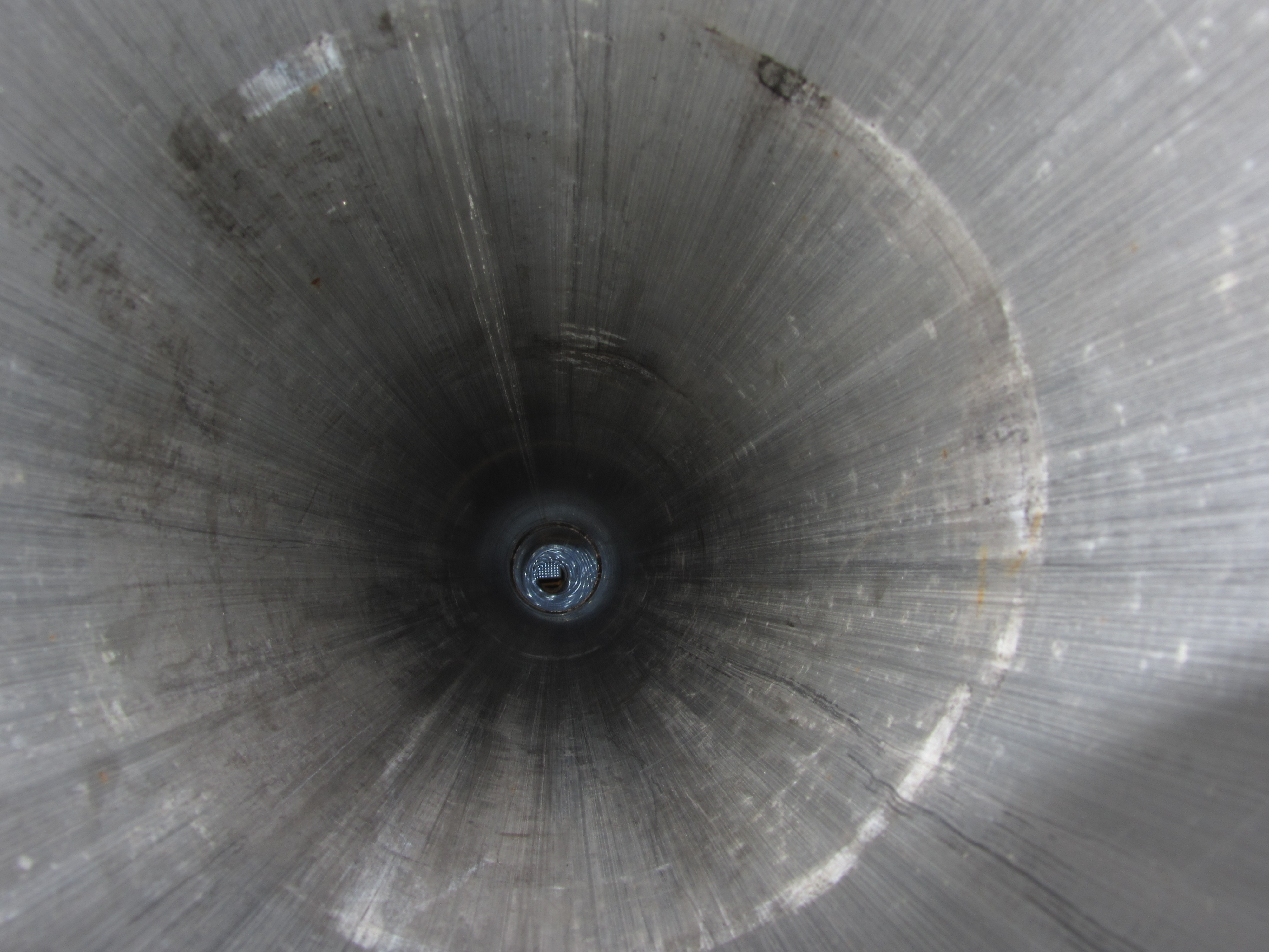
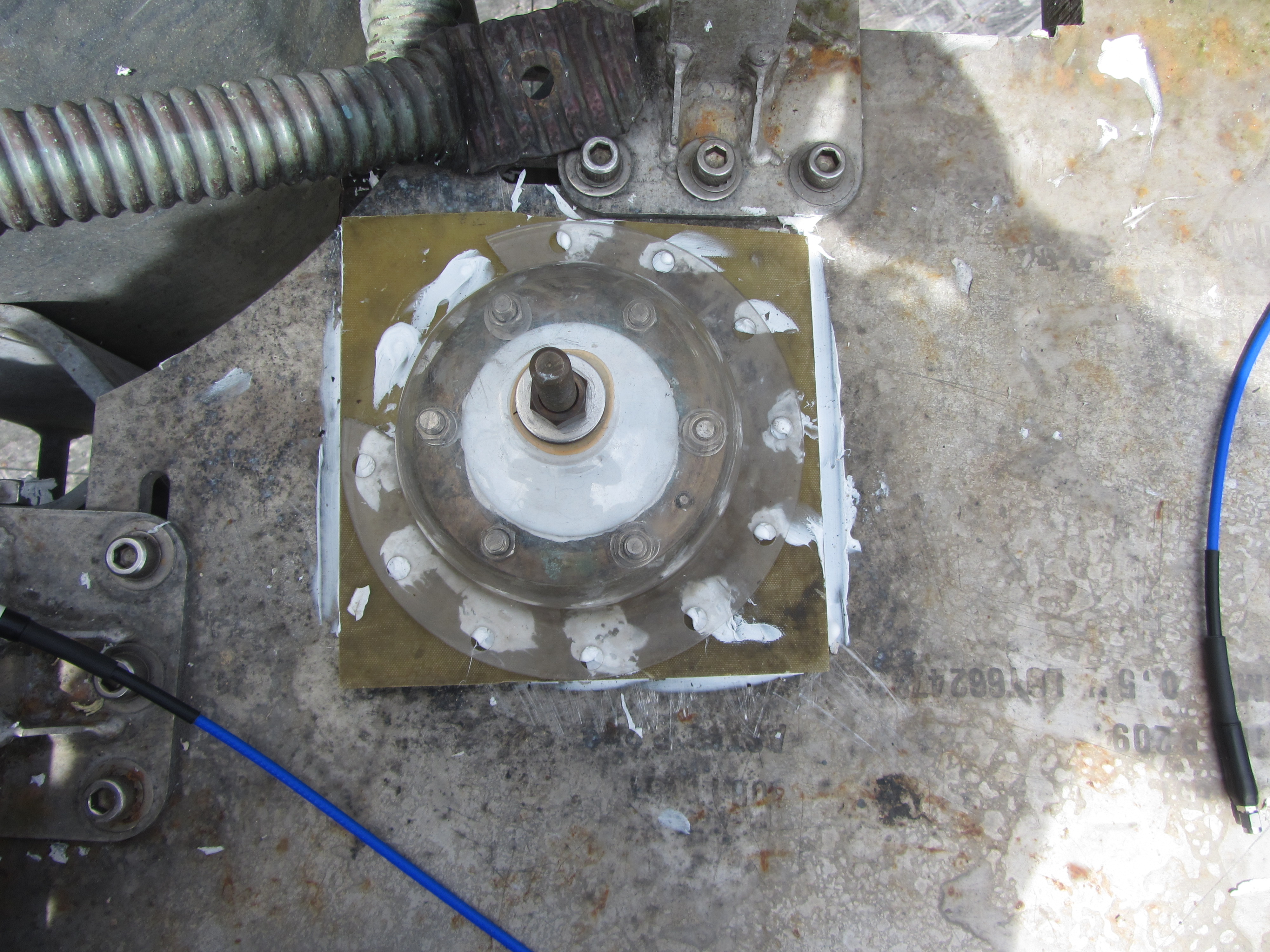
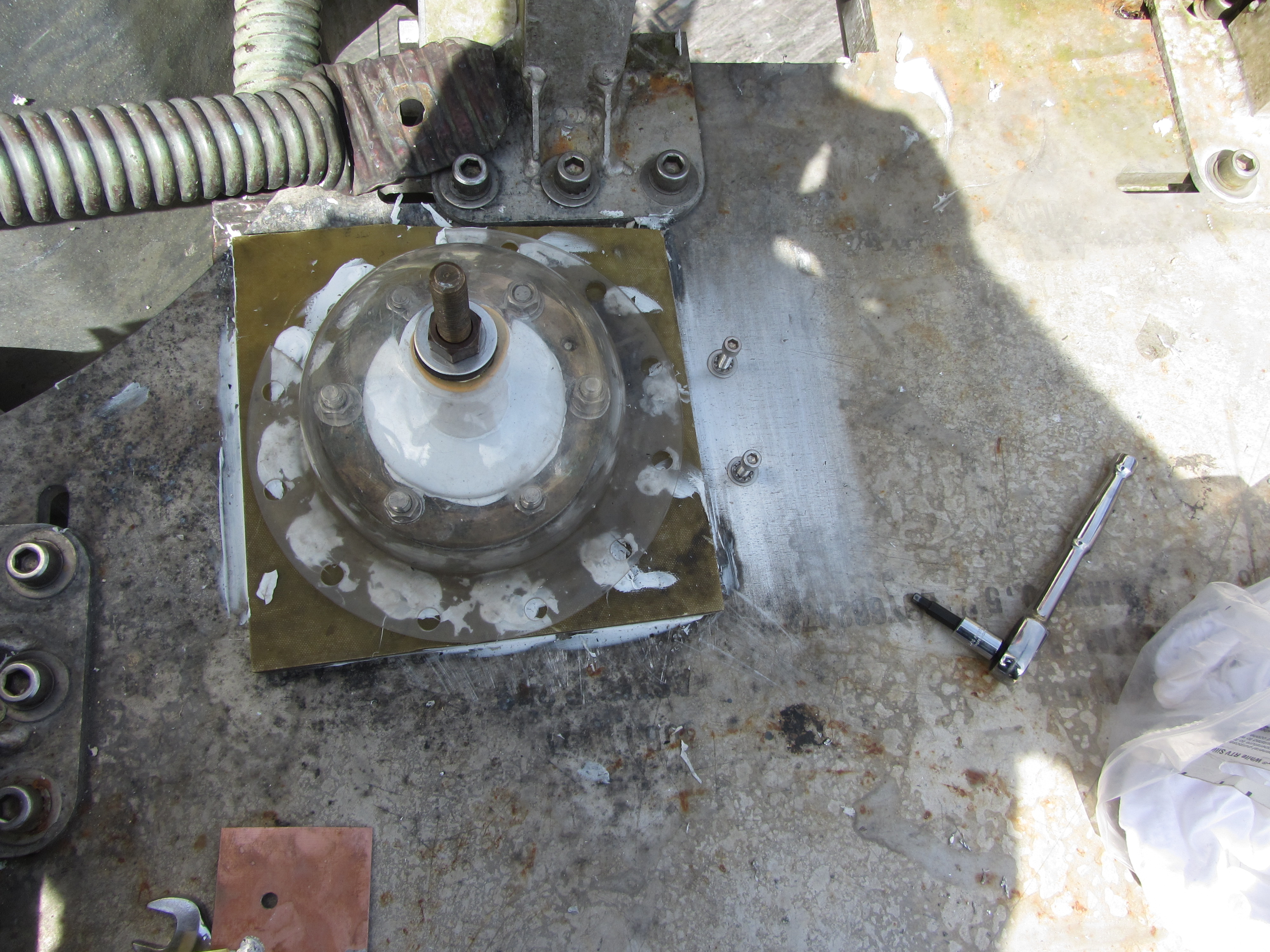
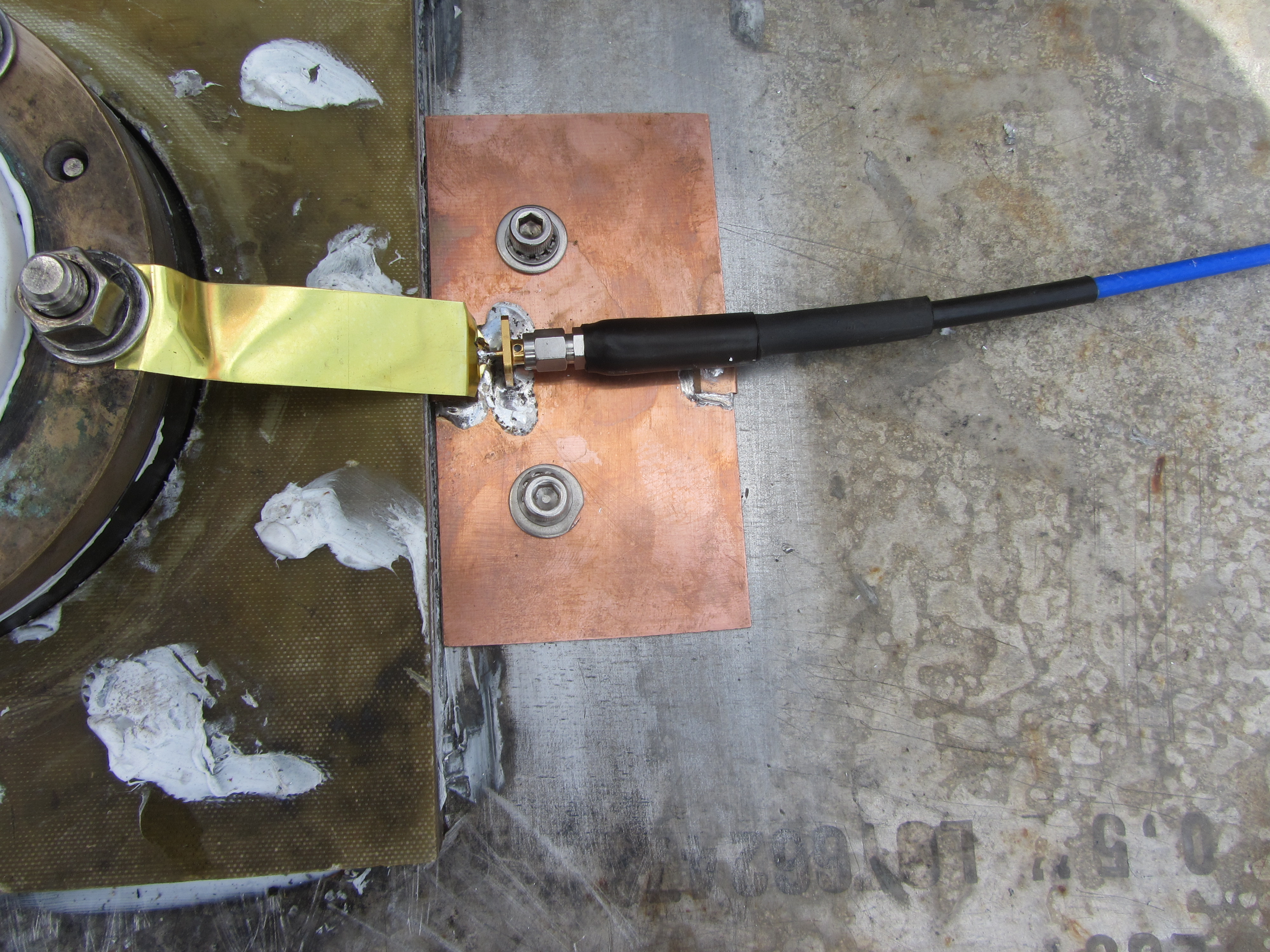
- 150930: pictures of
heliaxconnector at top of balun, adapter for vna measurement,
heliax connection to dipole.
- for more info on vna measurement see here.
- pict1: heliax
connector at top of balun. With plastic dome in place.
- The post sticking up connects to the heliax center
conductor.
- The bolts inside the edge of the plastic dome connect to
the heliax outer conductor.
- pict2: 2nd
shot of heliax connector at top of balun (with plastic dome in
place)
- You can see the cable that goes from the heliax
center conductor out to one half of the dipole.
- the two screws were added to mount the adapter board for
the vna measurement.
- pict3:
adapter connecting 70 foot vna cable to outer conductor
of heliax.
- The 70foot sma cable was calibrated. We used the
blue 8 foot cable (seen in the picture) to push the returned
echo away from the calibration 0 distance.
- pict4: cable
connecting center of balun to dipole half.
<-
page up
home_~phil